|


RAD Data Communications
DXC Family / DXC-8R / DXC-10A / DXC-30
Multi-Service Access Nodes
Features of the RAD DXC Family / DXC-8R
/ DXC-10A / DXC-30
 | RAD DXC family offers programmable non-blocking cross-connection (
DACS ) of up to 960 DS0s in some units
| Supports E3, T3, E1, T1, n x 56/64 and ISDN services over copper, IDSL,
HDSL and fiber media
| The modular RAD DXC family includes the following chassis types:
 | DXC-30 with 15 I/O modules
| DXC-30E with 15 6U-high I/O modules
| DXC-10A with 5 I/O modules
| DXC-8R with 4 I/O modules |
| | |
| Optional redundancy for common logic and power supply
| 1:1 protective switching
| E1/T1 conversion supports A-law/µ-law and signaling conversion
| Transmission of T1 traffic over E1, complying with ITU-T G.802
| Traffic grooming into E3/T3 uplinks
| Broadcast support with the RAD DXC
| Inverse multiplexing module supports up to 8 E1/T1 trunks
| Controlled slip buffer for overflow/underflow
| TFTP support for common logic software upgrade
| Test and monitoring at any port
| Management:
| Out-of-band via V.24 supervisory port or Ethernet management port
| Inband via TS 0 or dedicated timeslot |
|
| RADview SNMP management system on PC or UNIX (HPOV) platform
| Telnet support
| Separate dial-in/dial-out port
| Supports SNMP agent and standard management protocols: SLIP, PPP and
RIP2
| Local loop access solution with LTU or CSU options for extended range,
built-in fiber optic, or 2-wire/4-wire HDSL modems |
| | | | | | | | | | | | | | | | | |
RAD DXC Family / DXC-8R
/ DXC-10A / DXC-30 Description
| The DXC family of modular Multiservice Access Nodes provides
non-blocking cross connection ( DACS ) of up to 960 DS0s for up to 120 fractional
E1/T1 ports. DXC supports built-in local loop solutions. Plug-in
interface modules supporting n x 56/64 kbps, E1, T1, E3 or T3
transmission over copper, fiber or HDSL, are available. Also available
is the DIM module which provides inverse multiplexing capabilities of up
to 8 x E1, 8 x T1. |
| Typical applications for the DXCs: |
| Providing local loop access solution together with traffic grooming,
re-directing voice and data to different trunks (see Figure 1). |
| Concentrating multiple E1/T1 lines from a cellular base station
(BTS) onto a full E1/T1 link to the mobile switch center (MSC) (see
Figure 2). |
| Providing conversion/gateway between E1 and T1 networks for both
data and voice (see Figure 3). |
| In order to support the needs of different applications, the DXC
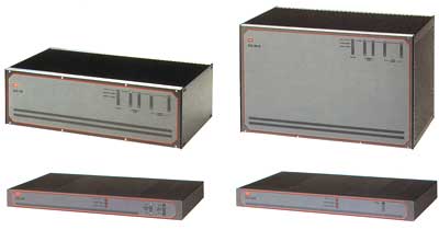
family features four unit variants: |
| DXC-30 (3U high) chassis with 15 I/O module slots |
| DXC-30E (6U high) chassis with 15 I/O module slots |
| DXC-10A (1U high) chassis with5 I/O module slots |
| DXC-8R (1U high) chassis with 4 I/O module slots. |
All units can be mounted in 19" racks.
CROSS CONNECTING ( DACS ) with the RAD DXC
| DXC-30 supports up to 120 E1/Fractional E1, T1/Fractional T1 or up to
30 n x 56/64 kbps ports. The RAD DXC-10A supports up to 40 ports, while the
smaller DXC-8R supports up to 32 ports. A user-programmable connection
table connects any incoming 64 kbps timeslot to any outgoing 64 kbps
timeslot. Support is provided for drop & insert and broadcast. |
| Cross-connection of n x 56 kbps or n x 64 kbps channels is implemented
by placing the data onto an E1 or T1 frame, using only the required
number of timeslots. This provides Fractional CSU/DSU functionality. |
| 1:1 protection through dual cable at the port level (same module)
ensures less than 50 msec link redundancy. Y-cable redundancy between
modules protects the service from hardware failure. |
E1/T1 CONVERTER
| DXC can function as a converter between E1 ports and T1 ports: |
| DXC-30/30E converts between up to twelve E1 and fifteen T1 ports |
| DXC-10A converts between up to four E1 and five T1 ports |
| DXC-8R converts between up to four E1 and four T1 ports. |
| A-law/µ-law and signaling conversion is performed according to the E1
and T1 standards. |
BASIC UNITS
| The basic DXC-30 (DXC-30E) unit includes one power supply, one common
logic module (DCL.2) and fifteen I/O slots for the plug-in interface
modules. Optional redundancy for the common logic and power supply is
available. |
| The basic DXC-10A unit includes one power supply, one common logic
module (DCL.2) and five I/O slots for the additional plug-in interface
modules. |
| The basic DXC-8R unit includes two power supplies and two common logic
modules (DCL.2) for system redundancy. DXC-8R has four I/O slots for the
plug-in interface modules. |
| Various timing options cover all timing possibilities for the E1/T1
interface. These include internal clock, external station (master)
clock, and loopback timing from any selected E1/T1 or n x 56/64 kbps
port. |
COMMON LOGIC
| The DCL.2 common logic module stores the matrix configuration and
event information, as well as configuration for alarm masking. It
communicates with the management station using a SLIP/PPP/Ethernet
connection (by means of an SNMP agent). DCL.2 can pass management
information received from 30 remote sites over a single dedicated
timeslot or TS 0, to the central management site. Flash for software
download, Telnet and ASCII terminal management are also supported. |
I/O MODULES
| DT1B and DT1, the two-port T1 interface modules, support
both D4 or ESF framing formats and AMI line code (zero suppression is
selectable for either Transparent, B7ZS or B8ZS). For long range
applications, a CSU option is available. DT1B additionally
provides BERT, loopback per timeslot, and 1:1 redundancy. DT1B is
available with either copper or fiber optic interfaces. |
| DE1B and DE1, the two-port E1 interface modules, support
both 2 and 16 frames per multiframe formats (256N and 256S,
respectively), TS 0 multiframe with CRC-4 and HDB3 line code. For long
range applications, an LTU option is available. DE1B additionally
provides BERT, loopback per timeslot, and 1:1 redundancy. DE1B is
available with either copper or fiber optic interfaces. |
| DT3, the single-port T3 interface module, supports multiplexing
of up to 28 T1 channels into a T3 frame with C-bit parity per ANSI
T1.404, or M13 framing options. DT3 is available with either copper or
fiber optic interfaces. |
| DE3, the single-port E3 interface module, supports multiplexing
of up to 16 E1 channels into an E3 frame per ITU-T G.751. DE3 is
available with either copper or fiber optic interfaces. |
| DHS, the two-port n x 56/64 kbps data module, provides two high
speed synchronous data channels. Each channel is independently selected
for either V.35 or V.11/RS-422 interface. Each channel can support bit
rates of n x 56 kbps, or n x 64 kbps, where:
n = 1 to 24 for T1
n = 1 to 31 for E1.
|
| DIM, the Digital Inverse Multiplexer module, working in
conjunction with DE1, DE1B, DT1, DT1B, DE3, DT3, D8E1 or D8T1 interface
modules, enables DXC to function as an inverse multiplexer. DIM allows
transmission of high speed signals over up to eight E1/T1 lines. This is
achieved by breaking down the high speed signals over the multiple E1/T1
lines and routing these signals over different paths or facilities,
while ensuring transmission integrity. |
| DHL/E1, the two-port HDSL module, uses HDSL technology to
extend the range of the DXC up to 4.0 km (2.5 miles) over 24 AWG (0.5
mm), 4-wire copper cable. It works opposite other RAD products with HDSL
technology (such as HCD-E1, HTU-E1, HTU-E1L, HTU-2 and Megaplex-2100
with ML-H modules). DHL/E1 complies with ITU-T G.704 and ETSI ETR-152
standards. |
| DHL/E1/2W, the two-port HDSL module, uses HDSL technology to
extend the range of the DXC up to 3.0 km (1.9 miles) over 24 AWG (0.5
mm), 2-wire copper cable. It can work in conjunction with the HCD-E1/2W,
to extend the range of the traditional subscriber loop while saving on
the copper infrastructure. DHL/E1/2W complies with ITU-T G.704 and ETSI
ETR-152 standards. |
| DHL/T1, the two-port HDSL module, uses HDSL technology to
extend the range of the DXC up to 4.0 km (2.5 miles) over 24 AWG (0.5
mm), 4-wire copper cable. It works opposite other RAD products with HDSL
technology (such as HTU-T1, HTU-T1L and Megaplex-2100/2200 with MLH and
HSH modules). DHL/T1 complies with ITU-T G.704 and ANSI T1E1.4. |
| D4E1/D8E1, the four or eight-port E1 interface module, provides
4 or 8 E1 links over copper cable supporting E1 or Fractional E1 rates. |
| D4T1/D8T1, the four- or eight-port T1 interface module,
provides 4 or 8 T1 links over copper cable supporting T1 or Fractional
T1 rates. |
| D8U/D16U, the 8 or 16-port ISDN "U" interface module,
provides independent ISDN "U" ports, each supporting 2B + D
channels, for total payload data rate up to 128 kbps per port. D8U/D16U
can be configured either to extend ISDN lines over non-ISDN facilities
(/I mode) or as dedicated line termination unit for the ASM-31 or
ASMi-31 short-range modems. |
MANAGEMENT & DIAGNOSTICS
| Setup, control and diagnostics can be performed out-of-band via a V.24
supervisory port or optional Ethernet management port using an ASCII
terminal with SLIP or PPP protocols. A built-in SNMP agent enables
remote management for configuration and diagnostics of remote devices
(up to 30 remote locations) using TS 0, a dedicated timeslot of E1/T1
trunk, or Telnet. |
| DXC provides diagnostic loopback support for each E1/T1 and n x 56/64
kbps module. DT1B/DE1B modules support loopbacks per timeslot including
an internal BERT, loopbacks toward the local or remote DTE, and PLB or
LLB code injection per ANSI T1.403. |
| Any port can be configured to test and monitor data on any given port
of the enclosure. |
| Enhanced statistics include T1 ESF diagnostics according to ANSI
T1.403 and AT&T 54016 (Local Support); E1 CRC-4 diagnostics per ITU-T
Rec. G.706 are performed in a manner similar to AT&T Pub. 54016. |
| A separate dial-in/dial-out port supports remote configuration
(dial-in) and automatic alarm indication (dial-out). For dial-out
operation, an external modem is activated to automatically dial a
pre-programmed number whenever an alarm event occurs. |
| Multiple DXC hubs can be managed by either a UNIX-based or PC-based
SNMP management system. The SNMP application is user-friendly, GUI-based
and runs under PC/Windows (RADview-PC/TDM) or HP OpenView UNIX (RADview-HPOV/TDM)
systems.
In addition, configuration and monitoring is provided via Telnet or a
dumb terminal. |
| Network management provides centralized control of all network nodes,
including interface configuration, connection setup, alarm and
management. Alarm status and system configurations are available at all
times. |
| Programming and setup of a remote DXC is done either: |
| Via TS 0 |
| Through the supervisory port of the remote unit, over a modem link,
or over a FRAD |
| Over a full inband dedicated timeslot, supporting FR, PPP and RIP2
standard protocols. |
Applications for the RAD DXC Family / DXC-8R
/ DXC-10A / DXC-30
Figure 1. Multiservice Access Platform
Figure 2. Bandwidth Optimization in a GSM Network using DXC-8R
Figure 3. E1/T1 Conversion and Access to Carrier Backbone
Ordering the RAD DXC products
Basic units and I/O modules, as well as any additional System
modules, are ordered separately.
BASIC UNITS
DXC-30-1/?/*/~/!
Basic unit includes 3U high chassis, one power supply and one DCL.2 common
logic module (no I/O modules)
DXC-30E-1/?/*/~
Basic unit includes 6U high chassis, one power supply and one DCL.2 common
logic module (no I/O modules)
DXC-10A-1/?/~/!
Basic unit includes 1U high chassis, one power supply and DCL.2 common
logic module (no I/O modules)
DXC-8R-1/?/~
Basic unit includes 1U high chassis, two power supplies, two DCL.2 common
logic modules (no I/O modules)
RAD DXC SYSTEM MODULES
DXC-30-CL.2/?
DCL.2 Common Logic No.2 Module with enhanced management, FLASH EPROM for
upgrade
DXC-30E-CL.2/?
DCL.2 Common Logic No.2 Module with enhanced management, FLASH EPROM for
upgrade for DXC-30E (6U high)
DXC-30-PS/~
Power supply module
DXC-30E-PS/~
Power supply module for DXC-30E
See separate data sheets
ORDERING OPTIONS FOR THE RAD DXC
? Specify management port interface:
V24 for V.24/RS-232 dial port
UTP for Ethernet 10BaseT
BNC for Ethernet 10Base2
* Specify R for power supply and
common logic redundancy
~ Specify power supply:
AC for 100 to 240 VAC operation
24 for +24 VDC operation (DXC-30 only)
48 for -48 VDC operation
! Specify N3 for NEBS-3 compliant chassis
Additional links with specific components:
| DXC-10A-1/48 10 CH DACS W/ENHANCED MGMT |
| DXC-10A-1/E1/230/TDS T1 TO E1 R2MFC
CONVERSION |
| DXC-10A-1/U/48 10 CH. DACS W/ ENHANCED MGMT
W/ ETH UTP |
| DXC-10A-1/U/AC 10 CH DACS W/ENHANCED MGMT W/
ETH UTP |
| DXC-10A-1/U/T1B/1/C ORDER:DXC-10A-1/U/AC
& DXC-M/T1B ETH |
| DXC-10A-1/UTP/48/N3 10 CH DACS W/ NEBS 3
COMPLIANCE |
| DXC-10A-1/V24/AC 10 CH DACS W/ ENHANCED
MGMT |
| DXC-10A/E1/115/C 10 CH DACS W/2 E1
INTERFACE +LTU |
| DXC-10A/E1/230 10 CH DACS W/TWO E1
INTERFACES |
| DXC-10A/E1/230/C 10 CH DACS W/2 E1
INTERFACE +LTU |
| DXC-10A/E1/48 10-CH.DACS W/TWO E1 INTERFACES |
| DXC-10A/E1/48/C 10 CH.DACS W/2E1 INTRFACES
<U 48V |
| DXC-10A/T1/230 10 CH DACS (INCLUDES 2 T1
INTERFACE) |
| DXC-10A/T1/48 10 CH.DACS WITH 2 T1 INTERFACES
AND 48V POWER |
| DXC-10A/T1/C 10 CH DACS [INCLUDES 2T1
INTERFACES] W/CSU 115 V |
| DXC-10M-T N.L.A. FOR M.C.I.ONLY T1 INTERFACE MOD
DXC-10 |
| DXC-30 30 CH DACS(WITHOUT T1/E1 INTERF) |
| DXC-30-1 30 CH DACS W/O T1/E1 LINKS W/ENHANCED
MANAGEMENT |
| DXC-30-1/48 30 CH. DACS W/O E1/T1 LINKS W/
ENHANCED MGMT. |
| DXC-30-1/MN 30 CH DACS - NO CL, NO PS |
| DXC-30-1/R 30 CH DACS W/O T1/E1 LINK W/ENHANCED
MGMT REDUNDANT |
| DXC-30-1/U 30 CH DACS W/O IO MODULE W/ENHANCED
MGMT & |
| DXC-30-1/U/48 30 CH. DACS W/O I/O MODULES
W/ENHANCED MGMT |
| DXC-30-1/U/R 30 CH DACS W/O IO MODULES
W/ENHANCED MGMT & |
| DXC-30-1/U/R/48 30 CH DACS W/O T1/E1 LINK
REDUNDANT ENHANCED |
| DXC-30-1/UTP/R/48/N3 30 CH. DACS W/ NEBS
3 COMPLIANCE |
| DXC-30-1/V24/R/48 30 CH DACS W/O E1/T1
LINKS W/ENHANCED MGMT |
| DXC-30-3/UTP/R/48 30 CHANNEL DACS W/ CL.3
COMMON LOGIC |
| DXC-30/48 30 CH DACS(WITHOUT T1/E1 INTERF) |
| DXC-30E-1/U/R/AC 30 CH DACS INCL 6U HIGH
CHASSIS |
| DXC-30E-1/UTP/AC DIGITAL CROSS CONNECT W/
15 6U HIGH SLOTS |
| DXC-30M-CL.2/UTP COMMON LOGIC MODULE W/UTP
INTRFC |
| DXC-30M-CL.2/V24 COMMON LOGIC MODULE FOR
DXC-30-1 |
| DXC-30M-FT/48 DC FAN TRAY FOR DXC-30 |
| DXC-30M-PS-AC POWER SUPPLY |
| DXC-30M-PS/48 POWER SUPPLY 48VDC |
| DXC-30M-PS/AC POWER SUPPLY |
| DXC-8R-1/48 8 CHANNEL DACS REDUNDANT W/O T1/E1
LINKS |
| DXC-8R-1/UTP DXC-8R WITH CL2 / UTP |
| DXC-8R-1/UTP/48 E1/T1 CONVERTER BETWEEN 12
E1 & 16 T1 |
| DXC-8R-3/V24/AC 8 CHANNEL DACS |
| DXC-8R/48 8 CHANNEL DAC REDUNDANT W/O T1/E1
LINKS |
| DXC-M-T1/FO1 T1/FIBER OPTIC INTERFACE MODULE
FOR DXC |
| DXC-M/4E1/B 4 PORT E1 MODULE, BALANCED FOR
DXC-30 |
| DXC-M/4E1/U 4 PORT E1 MODULE, UNBALANCED FOR
DXC-30 |
| DXC-M/4T1 4 PORT T1 MODULE FOR DXC-30 |
| DXC-M/8E1/B 8 PORT E1 MODULE BALANCED FOR
DXC-30 |
| DXC-M/8E1/U 8 PORT E1 MODULE UNBALANCED FOR
DXC-30 |
| DXC-M/8T1 8 PORT T1 MODULE FOR DXC-30 |
| DXC-M/8U 8 PORT ISDN INTERFACE MODULE FOR DXC-30 |
| DXC-M/DIM/E1 DIGITAL INVERSE MUX MODULE FOR
DXC |
| DXC-M/DIM/ETU DIGITAL INVERSE MUX MODULE FOR
DXC |
| DXC-M/DIM/HSSI DIGIATL INVERSE MUX MODULE |
| DXC-M/DIM/V35 DIGITAL INVERSE MUX MODULE |
| DXC-M/DSP/TDS T1 TO E1 R2MFC CONVERSION |
| DXC-M/E1/FO3 E1 FIBER OPTIC MODULE FOR DXC
(1300NM ST CONN) |
| DXC-M/E1/H HDSL E1 LINK MODULE, 3U HIGH VERSION |
| DXC-M/E1/H/2W 2 WIRE HDSL E1 LINK MODULE, 3U
HIGH VERSION |
| DXC-M/E1/ST85 E1 FIBER MODULE, ST CONN, 850NM |
| DXC-M/E1/TDS T1 TO E1 R2MFC CONVERSION |
| DXC-M/E1A 2 PORT E1 MODULE FOR DXC-30 |
| DXC-M/E1B 2 PORT E1 INTERFACE MODULE W/LOOPBACK
PER TIMESLOT |
| DXC-M/E1B/C 2 PORT E1 INTERFACE MODULE W/LOOPBACK
PER |
| DXC-M/E3 E3 MODULE FOR DXC-30 |
| DXC-M/HS/530 HIGH SPEED DATA MODULE FOR DXC |
| DXC-M/HS/V35 HIGH SPEED DATA MODULE FOR DXC-30 |
| DXC-M/R2/BRSL-WA BRAZIL SIGNALING CHANGE OF
WINK START OF A |
| DXC-M/R2/MCX-1A MEXICO SIGNALING CHANGE ON A
BIT OF E1/T1/ONLY |
| DXC-M/R2/MXC-1B MEXICO SIGNALING CHANGE ON B
BIT OF T1/E1 ONLY |
| DXC-M/R2/MXC-WA MEXICO SIGNALING CHANGE ON
WINK START OF A BIT |
| DXC-M/R2/MXC-WB MEXICO SIGNALING CHANGE OF
WINK START OF B BIT |
| DXC-M/T1/FC/13 T1 FIBER OPTIC MODULE FOR
DXC-30 |
| DXC-M/T1/FO3 T1/FIBER OPTIC INTERFACE MODULE
FOR DXC |
| DXC-M/T1/FO6 T1/FIBER OPTIC INTERFACE MODULE
FOR DXC |
| DXC-M/T1/FO8 FIBER MODULE FC13L FOR DXC-30 |
| DXC-M/T1/H HDSL T1 LINK MODULE |
| DXC-M/T1/TDS T1 TO E1 R2MFC CONVERSION |
| DXC-M/T1B DTI 2 PORT T1 INTERFACE MODULE W/BERT
& |
| DXC-M/T1B/BP T1 MODULE FOR DXC-30 |
| DXC-M/T1B/C DTI 2 PORT T1 INTERFACE MODULE
W/BERT & |
| DXC-M/T3 T3 INTERFACE MODULE FOR DXC |
| DXC-M/T3/747 T3 MODULE, G747 COMPLIANT |
| DXC-M/T3/ST13 T3 FIBER MODULE FOR DXC |
| DXC-ME/8E1/B 8 PORT E1 INTERFACE MODULE, 6U
HIGH VERSION |
| DXC-ME/8T1 8 PORT T1 INTERFACE MODULE, 6U HIGH
VERSION |
| DXC-STM-1-3/UTP/R/48/FC13L 7U HYBRID
VERSION OF DXC-30 & |
DXC data sheet (342k pdf)
DXC T1 module data sheet (491k pdf)
DXC E1 module data sheet (538k pdf)
DXC operations manual (4,270k pdf)
Octal V35 module data sheet (pdf)
|