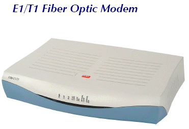


FOM-E1/T1 Fiber Optic Modem from RAD
The FOM-E1/T1 - FOM-E1T1 fiber optic modem from RAD converts E1 / T1 electrical signals into optical signals. After the conversion, the signals are transmitted over fiber optic cables, extending the E1 / T1 service range up to 144 km (89.4 miles).

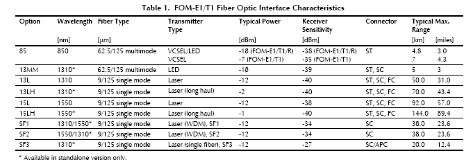
FOM-E1/T1 fiber optic modem supports various optical interfaces:
- 850 nm for multimode fiber
- 1310 nm for multimode fiber
- 1310 nm for single mode fiber
- 1550 nm for extended range over single mode fiber.
FOM-E1T1 fiber optic modem operation complies with ITU G.703 and G.955 standards.
- The modem supports activation of local and remote loopbacks.
- Alarm relay port transmits the following alarm conditions:
- Major alarm Low level of E1/T1 electrical input or high bit error rate at the fiber optic interface
- Minor alarm AIS received at electrical or fiber optic interface.
- Front panel LEDs indicate system faults in the electrical and fiber optic circuits.
- FOM-E1/T1 is also available as a plug-in card for RADs ASM-MN-214, 19-inch card cage.
Features of the FOM-E1/T1 fiber optic modem from RAD:
Fiber optic modem, extending the range of E1/T1 services over fiber optic cables up to 144 km (89.4 miles)
Transparent to E1/T1 framing
Operates opposite RAD's DXC cross-connect system, Megaplex access multiplexers and FCD access units
Available with laser diode option for extended ranges
Conforms to all relevant ITU series standards
Operates over single mode or multimode fibers
Relays minor and major alarm conditions
Features front panel LED indicators for status monitoring
Specifications of the FOM-E1T1 fiber optic modem:
E1/T1 ELECTRICAL INTERFACE
Transmission Rate
- E1: 2.048 Mbps
- T1: 1.544 Mbps
Zero Suppression
- E1: HDB3
- T1: B8ZS, AMI
Impedance
E1: 75O unbalanced or 120O balanced
T1: 100O balanced
Connectors of the FOM-E1/T1 fiber optic modem:
Balanced: RJ-45
Unbalanced: BNC
FIBER OPTIC INTERFACE
Specifications, ranges, and
connectors
See Table 1
General Information on FOM-E1 / T1 fiber optic modem
- Diagnostics Local and remote loopbacks activated via back panel DIP switch
- Alarm Relay Port Dry contact via 9-pin, D-type, female connector
- Indicators
PWR (green) Power
LLB (yellow) Local loopback
RLB (yellow) Remote loopback
OPTICAL AIS (yellow) "All 1s" string received at the fiber optic interface
OPTICAL LOSS (red) BER is over 10-6
ELEC LOSS (red) Electrical interface input is below G.703 level
ELEC AIS (yellow) "All 1s" string received at the electrical interface
Power options for the RAD FOM-E1/T1 fiber optic modem
AC: 100240 VAC nominal
DC: 48/60 VDC nominal or
24 VDC
- Power Consumption
AC: 3 VA max
DC: 4W max
- Physical
Height: 43.7 mm / 1.7 in
Width: 240 mm / 9.4 in
Depth: 170 mm / 6.7 in
Weight 0.5 kg / 1.1 lb
Environment
Temperature: 050°C/32122°F
Humidity: Up to 90%,
non-condensing
Ordering Options for the FOM-E1/T1 fiber optic modem from RAD
FOM-E1/T1/*/#/& E1/T1 fiber optic modem
FOM-E1/T1/R/#/& E1/T1 fiber optic modem, card version for ASM-MN-214 card cage
* Specify power supply type:
AC for 100240 VAC
48 for 48 VDC
24 for 24 VDC
# Specify fiber optic connector type:
ST for ST connector
SC for SC connector
FC for FC connector
& Specify the optical wavelength, fiber
and transmitter type (see Table 1):
85 for 850 nm, multimode, VCSEL
13MM for 1310 nm, multimode, LED
13L for 1310 nm, single mode, laser diode
13LH for 1310 nm, single mode, laser diode, long haul
15L for 1550 nm, single mode, laser diode
15LH for 1550 nm, single mode, laser diode, long haul
SF1 for WDM single fiber, 1310 nm Tx
SF2 for WDM single fiber, 1550 nm Tx
SF3 for single fiber, 1310 nm Tx/Rx
RM-33 kit: Hardware for mounting one RAD FOM-E1/T1 fiber optic modem unit in a 19-inch rack.

FOM-E1T1
- data sheet (pdf 524k)
FOM-E1T1
Installation and operations manual (pdf 2187k)
Most common model: FOM-E1T1/AC/SC13L