|


Optimux-XLT1 from RAD
Multiple T1 and Ethernet Optical Multiplexer
Optimux-XLT1 Features
 | The RAD Optimux-XLT1 integrates multiple T1 and Ethernet channels over
a single link
 | Transmission over fiber optic cable
 | Supports multimode fiber, single mode fiber and single mode over
single fiber (WDM)
 | Laser diode option
 | Range up to 60 km (36 miles)
 | Conforms to ITU G.703, ANSI T1.102, G.742, G.751, G.823, G.956
 | Optional second fiber optic link provides automatic backup
 | The RAD Optimux-XLT1 can be ordered with an optional redundant power
supply
 | Management using ASCII terminal, Telnet or SNMP management station
 | Compact, 1U high enclosure |
| | | | | | | | |
RAD Optimux-XLT1 description
 | Optimux - XLT1 provides a simple, flexible and cost-effective solution
for transporting multiple T1 links and Ethernet at distances up to 60 km
(36 miles). |
 | Optimux - XLT1 integrates up to 12 T1 channels and up to four Ethernet
LANs over a single fiber optic link. This provides an easily upgradable
solution, flexible enough to meet the specific requirements of a broad
range of applications. |
 | The RAD Optimux-XLT1supports one fixed 10BaseT Ethernet port and three
additional plug-in channel modules. Available channel modules are:
|
 | Modules can be combined in various ways, ranging from four Ethernet
ports to a single Ethernet port with up to 12 T1 channels. |
 | Various optical interfaces are available:
 | 850 nm for multimode fiber
 | 1300 nm for single mode fiber
 | 1300 and 1550 nm laser for extended range over single mode fiber. |
| |
|
 | Two Optimux - XLT1 units can be connected over a single fiber (SF)
using the WDM technology (The transmit signal is at a different
wavelength than the receive signal). |
 | Where required, all critical components can be automatically backed
up. This ensures there is no single point of failure. An optional second
link provides backup, using automatic switchover upon link failure. An
optional second power supply provides power redundancy and fail-safe
operation. |
 | Ethernet data is transmitted using a built-in bridging function. The
bridge operates at 6 Mbps and supports up to 10,000 addresses. |
 | Optimux - XLT1 from RAD transmits each of the T1 channels independently, such
that the clock of each T1 channel is independent. |
 | To facilitate system diagnostics, Optimux - XLT1 features LED status
indicators, AIS alarm generation, recognition and dry contact closure
upon link failure. In addition, the Optimux - XLT1 setup, control and
diagnostics can be performed via a supervisory port using an ASCII
terminal. Telnet can also perform these operations via the Ethernet
ports or a dedicated separate Ethernet management port. |
 | The SNMP management application offers the following options:
 | Java-based Web management running on Netscape or Microsoft
Explorer
 | RADview - PC running in a Windows environment
 | RADview - HP for HPOV UNIX platforms. |
| |
|
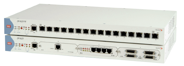
 | Optimux - XLT1 is available as a compact 1U high unit for mounting in
a 19" rack. |
Optimux-XLT1 Applications
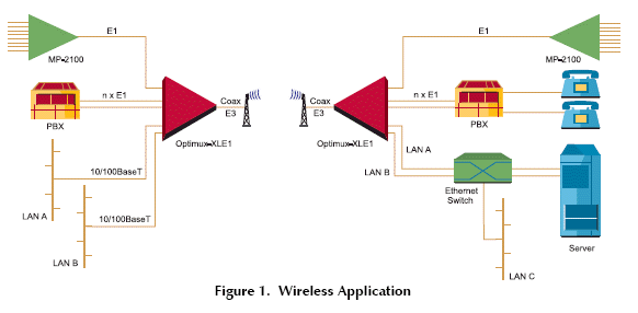
Figure 1. Point-to-Point Application

Optimux-XLT1 Ordering Options
OP-XLT1/*/R/#+/D
Multiplexer with built-in Ethernet port.
Note: All channel modules should be ordered separately
(see below).
| * |
Specify power supply
AC for 115/230 VAC
48 for -48 VDC
24 for 24 VDC |
| R |
Specify R for second redundant power supply (same type
as first) |
| #+ |
Specify Link interface
(# for connector type, followed by + for optical
wavelength) |
| # |
ST for ST type connector
SC for SC type connector
FC for FC type connector |
| + |
85 for 850 nm, multimode
13 for 1300 nm, single mode
13L for 1300 nm, single mode, laser diode
15L for 1550 nm, single mode, laser diode
SF1 for transmit 1300 nm, receive 1550 nm
SF2 for transmit 1550 nm, receive 1300 nm |
| Note: |
for single fiber connection (WDM) one of the devices has to
be ordered with SF1 interface and the other with SF2
interface. |
D Specify D for second redundant link (same type as first
link)
Channel Modules
OP-XL-M/4T1 for 4 x T1
OP-XL-M/ETH for 10BaseT Ethernet
Optimux-XLT1 data sheet (pdf)
|
